
Catatlah garis dasar dimensi yang dapat diulang sebelum meminta penggantian rantai.
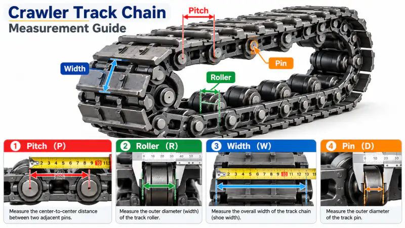
A sound replacement process starts by identifying the work the chain performs and the evidence available at the installation. The steps below are presented as a decision workflow. They do not assume that any two unmeasured components are interchangeable.
Clean The Measurement Points
Mud, scale and heavily worn corners can conceal the true centre of a pin. Clean enough surface to identify the actual joint axes without unnecessarily dismantling the assembly. If access is poor, state which numbers are approximate.
Measure Across Several Pitches
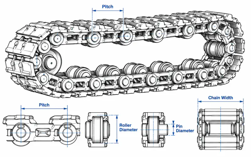
A single link may have elongated joint clearance. Measure over several equal pitch intervals, divide the span by the interval count and compare with one or two isolated pitches. The average is a screening measurement, not a substitute for a product drawing.
For this step, document the before-condition and the exact measurement or observation used to make the decision. If the part is already removed, show where it fitted by photographing adjacent components. Keep the photo identifier next to the measured value so it can be checked later.
Measure Joint Components
Record pin outside diameter, roller outside diameter, roller working width and inside link clearance where visible. Measure at more than one angular position when wear is uneven and do not assume a worn diameter equals the nominal manufactured size.
A supplier reviewing measure joint components must know whether the figure is nominal drawing data, field measurement, or an estimate from a worn component. That distinction changes what can be quoted without a sample and what needs an additional dimensional inspection.
Check The Attachment Pattern
Plate or cleat mounting holes form a second repeat pattern. Mark hole diameters, centre-to-centre distances, lateral offset and orientation. A matching main-chain pitch does not correct a different attachment layout.
For this step, document the before-condition and the exact measurement or observation used to make the decision. If the part is already removed, show where it fitted by photographing adjacent components. Keep the photo identifier next to the measured value so it can be checked later.
Send A Clear Dimensional Set
Provide a dimensioned photo, a legible sketch and the original machine identification. Include the number of links in the complete circuit if available, plus the sprocket photograph and operating environment.
Enquiry Data Checklist
| Masukan dari pembeli | Alasan untuk mengkonfirmasi |
|---|---|
| Machine context | Actual chain function, installation position, equipment model if known |
| Chain dimensions | Pitch across multiple joints, width and joint reference dimensions |
| Mounting interface | Attachment locations, hole pattern and sprocket relationship |
| Service context | Working medium, abrasion exposure and wear symptoms |
| Berkas | Measured sketch, installed photos, part reference, quantity |
Decisions That Require Verification
Manufacturing dimensions, material grade, heat treatment, permissible operating load and any substitute part reference have to be confirmed for the real ordered configuration. General chain geometry can support preliminary identification but cannot establish a guaranteed replacement by itself.
Even when a nominal chain pitch is known, examine the mating assembly. A repair that restores one joint but leaves severely worn sprocket teeth or distorted brackets unchanged may not address the underlying fault. Distinguish immediate maintenance work from a complete system replacement decision.
Technical Review Workflow
- Identify the machine function and which component is being discussed.
- Record the measured geometry with photographs and units.
- Check the mating chain, sprocket and attachment interface.
- Define the exact replacement scope and quantity.
- Submit the sketch and photos for configuration review.
Common Questions
What if the original part number is missing?
Use installed-machine views, a measured chain sample, photographs of the connecting components and a description of the duty.
Is a matching pitch enough to place an order?
No. Joint shape, width, roller geometry, mounting offset and sprocket engagement can differ at the same nominal pitch.
Can dimensions from a worn component be used?
Yes as a provisional starting point, but significant wear must be documented and compared with an unworn reference when possible.
How can a technical enquiry be reviewed efficiently?
Supply the actual application, photos with scale, readable sketch, link count, interface details and quantity.
Prepare The Part For Measurement
Clean the accessible chain surface enough to identify joint centers without altering the part. Keep the machine in its documented safe maintenance condition before reaching around sprockets or undercarriage components. Mark one starting joint and count several consecutive pitches along a relatively straight section. A digital caliper may work for accessible small features, while a suitable rule or tape can be more practical over multiple large links. Record the measuring tool and unit system. Photograph the scale directly alongside the joint so another reviewer can see what was measured.
Choose Multiple Pitch Samples
An isolated pin-to-pin reading on a worn chain can be distorted by surface wear, pin clearance or a tilted measuring tool. Measuring across several consecutive joints helps reveal whether one local joint is damaged or the entire strand has elongated. Note the number of intervals between the first and last marked joint, and keep those marks visible in a companion photo. If the chain is highly curved around a wheel, record that fact and move to a straight section for comparison where safe. Do not treat a field value as a nominal drawing tolerance.
Document Widths Separately
Inside width, outside width, roller or bush width and attachment spacing describe different features. Measure each from the correct datum and label the result so it cannot be mistaken for overall chain width. If two chains run parallel beneath a wide track, distinguish the spacing between strands from the width of an individual link. Include a side elevation for vertical offsets and a top view for hole positions. Avoid taking several numbers without a sketch: unlabelled values are difficult to translate into a manufacturing drawing later.
Handle Wear And Deformation
Take an additional measurement on an adjacent link that appears less damaged when possible. An oval pin hole, bent plate or flattened roller may no longer represent the intended manufactured profile. Report the measured condition honestly and identify what surface was used as the reference. If the original manufacturer drawing is unavailable, submit more views rather than guessing a standard code. Engineering review can then separate information suitable for identification from dimensions that require a fresh part or controlled sample.
Check The Installed Envelope
After recording nominal-looking dimensions, inspect the space the chain occupies during travel. Note nearby guards, guide rails, mounting brackets and any narrow turning radius. The allowable assembly width may be controlled by one local region rather than by the open straight run. Photograph the existing sprocket from the front and side, and show how the roller or link enters the tooth gap. A part with similar pitch may still fail on a different roller diameter or mounting offset. Include the envelope drawing with the chain dimensions.
Make The Drawing Actionable
A useful sketch has a clear title, units, orientation arrows, dimensions, photo references and an explicit list of unknown values. Separate the count of links from the overall circuit length. Mark whether the quantity requested represents one loose link, a joined strand or a pair of chains. Submit the sketch with at least one close-up image and one image showing the chain in the machine. This gives the manufacturer enough context to respond with targeted questions instead of interpreting unlabeled numbers.
Next Step
Use the measurement guides and product-family pages together. A clear enquiry record helps the technical team identify uncertainty before a replacement decision becomes expensive.