Understand what to record when a component is removed from an unfamiliar assembly.
Эффективный процесс замены начинается с определения выполняемой цепью работы и имеющихся на месте установки доказательств. Ниже представлены этапы, описывающие алгоритм принятия решений. Они не предполагают взаимозаменяемости любых двух неизмеренных компонентов.
Separate The Component Types
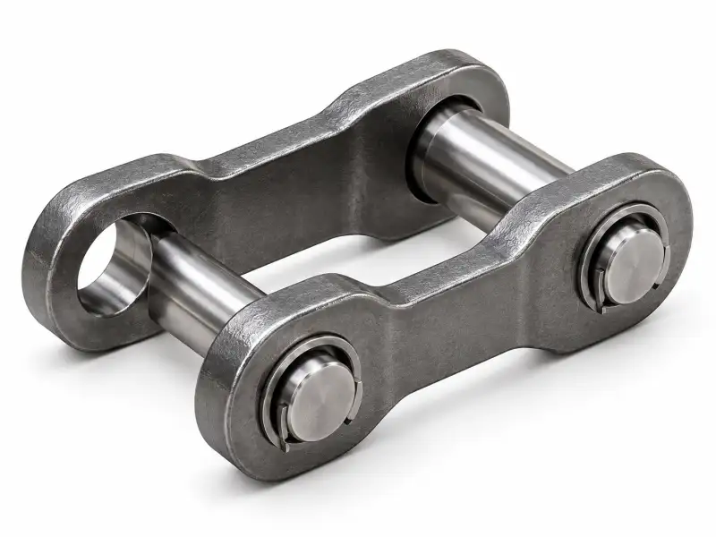
A link forms the repeated joint; a connecting element joins two structures; an attachment bracket supports something external; a plate may carry ground reaction or material. Determine the job before selecting a name.
Use An Orientation Sketch
Draw the machine direction, inner and outer chain faces and major bolt holes. This prevents a visually symmetric photograph from concealing a handed or offset component.
На этом этапе задокументируйте исходное состояние и точное измерение или наблюдение, использованное для принятия решения. Если деталь уже снята, покажите, где она была установлена, сфотографировав соседние компоненты. Сохраните идентификатор фотографии рядом с измеренным значением, чтобы его можно было проверить позже.
Collect Key Dimensions
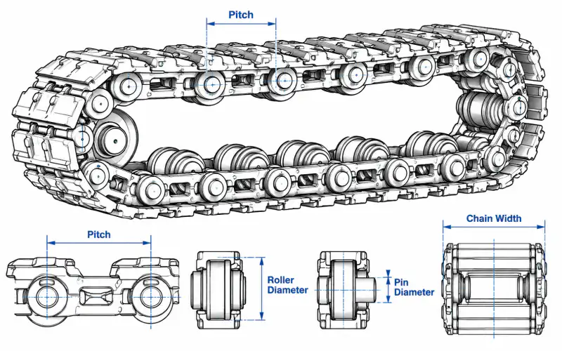
Mark pin centres, bore diameters, width between plates, component thickness, overall height and any special offsets. Include a scale and specify metric or imperial units.
A supplier reviewing collect key dimensions must know whether the figure is nominal drawing data, field measurement, or an estimate from a worn component. That distinction changes what can be quoted without a sample and what needs an additional dimensional inspection.
Check Adjacent Parts
Photograph the pieces that mate with the unknown component. A connection that looks standard may rely on a special spacer, end retainer or nonstandard boss.
На этом этапе задокументируйте исходное состояние и точное измерение или наблюдение, использованное для принятия решения. Если деталь уже снята, покажите, где она была установлена, сфотографировав соседние компоненты. Сохраните идентификатор фотографии рядом с измеренным значением, чтобы его можно было проверить позже.
Prevent Misclassification
Do not copy a type name from a catalogue image when the installed part serves a different machine function. Treat uncertainty as a technical question to resolve before procurement.
Контрольный список данных запроса
| Мнение покупателя | Причина для подтверждения |
|---|---|
| Машинный контекст | Фактическая функция цепи, место установки, модель оборудования (если известна). |
| Размеры цепи | Шаг стыков по нескольким соединениям, ширина и опорные размеры стыков. |
| Интерфейс крепления | Места крепления, расположение отверстий и взаимосвязь звездочек. |
| Контекст обслуживания | Рабочая среда, воздействие абразивного материала и признаки износа |
| Файлы | Эскиз с замерами, фотографии установленной детали, артикул, количество. |
Решения, требующие проверки
Для соответствия фактической заказанной конфигурации необходимо подтвердить габариты, марку материала, термообработку, допустимую рабочую нагрузку и любые ссылки на заменяемые детали. Общая геометрия цепи может служить для предварительной идентификации, но сама по себе не гарантирует замену.
Даже если известен номинальный шаг цепи, осмотрите сопрягаемый узел. Ремонт, восстанавливающий одно соединение, но оставляющий сильно изношенные зубья звездочки или деформированные кронштейны без изменений, может не устранить основную неисправность. Различайте немедленные ремонтные работы и решение о полной замене системы.
Рабочий процесс технической проверки
- Определите функцию машины и какой компонент рассматривается.
- Зафиксируйте измеренные геометрические параметры с помощью фотографий и единиц измерения.
- Проверьте сопряженную цепь, звездочку и место крепления.
- Укажите точный объем и количество заменяемых деталей.
- Отправьте эскиз и фотографии для проверки конфигурации.
Часто задаваемые вопросы
Что делать, если отсутствует оригинальный номер детали?
Используйте схемы установки оборудования, образец цепи с замерами, фотографии соединительных компонентов и описание выполняемой задачи.
Достаточно ли совпадения предложений для размещения заказа?
Нет. Форма соединения, ширина, геометрия роликов, смещение при монтаже и зацепление звездочки могут отличаться при одном и том же номинальном шаге.
Можно ли использовать размеры изношенной детали?
Да, это предварительная отправная точка, но значительные следы износа необходимо задокументировать и, по возможности, сравнить с неношеным экземпляром.
Как эффективно рассмотреть технический запрос?
Предоставьте описание самого приложения, фотографии в масштабе, разборчивый эскиз, количество ссылок, детали интерфейса и их количество.
Start With Mechanical Function
A chain component should be named according to the force or motion it handles, not only the way its silhouette looks. Determine whether it forms a repeating link, carries an attachment, joins two chain sections or interacts directly with a sprocket. Photographs may show substantial metal shapes but not the side that actually transmits force. A simple sketch with arrows for chain travel and load direction helps reveal the role. This is particularly important where catalogue pictures include both crawler and mining conveyor parts that share visually similar features.
Create An Orientation Record
Before removing the part, mark the outward face, machine side, direction of travel and connection to nearby plates. Photograph the fasteners and retainers before disassembly, keeping each image in a numbered sequence. With an unfamiliar assembly, pieces that appear mirror-symmetric may actually have offset bosses or hand-specific mounting faces. A labelled orientation record reduces the chance of ordering a part that physically matches one face but cannot be installed on the required side. Include a wide view of the mechanism to show what the detail belongs to.
Measure The Joint Profile
Record the distance between pin centers, inside and outside widths, plate thickness, pin-hole diameters and any shoulder lengths. On components with a mounted plate, add hole centers and vertical offsets from the chain joint axis. Avoid measuring only the longest visible dimension. A small change in an internal clearance can prevent articulation even where outside dimensions are similar. Keep worn values separate from drawing values and identify which surfaces show deformation. If the original nominal shape cannot be reconstructed safely, request an engineering review with the worn sample and related assembly drawings.
Inspect Connected Elements
No link works in isolation. A joint may include a pin, a bush, a roller, a spacer and retention hardware; a mounted attachment may also connect to a larger bar or plate. Assemble a simple parts map showing which items move together and which surfaces articulate. This helps distinguish a connecting link from a load-carrying bracket and reveals whether replacement parts should be ordered as a kit. When a chain guide or sprocket touches a particular surface, include that detail in the sketch because it can identify an otherwise ambiguous component.
Avoid False Interchange Claims
Matching an online photograph is a useful first step but is not a substitute for dimensions and mechanical compatibility. A replacement may share an outside profile yet differ at the pin axis, internal width or support contact point. Do not use brand names or nominal family labels to claim direct substitution without a checked drawing. In an enquiry, identify any missing values and the evidence available for verifying them. If one source image appears to represent a material conveyor part rather than a travelling track part, keep that uncertainty visible.
Organize The Final Package
Arrange the enquiry as machine overview, installed assembly, removed part views, dimensions, component count and required quantity. Use descriptive filenames and keep a concise list of open questions. If a workshop can supply a measured sketch, attach it alongside the unedited photographs. This provides enough context for a technical dialogue without implying that every part has already been identified. The resulting record can later become the basis for a model-specific product page once an approved configuration and real dimensions are confirmed.
Следующий шаг
Используйте руководства по измерениям и страницы, посвященные семействам продуктов, вместе. Четкая запись запросов помогает технической команде выявлять неопределенности до того, как решение о замене станет дорогостоящим.
Просмотреть семейства продуктов Отправить технические характеристики