Understand what to record when a component is removed from an unfamiliar assembly.
A sound replacement process starts by identifying the work the chain performs and the evidence available at the installation. The steps below are presented as a decision workflow. They do not assume that any two unmeasured components are interchangeable.
Separate The Component Types
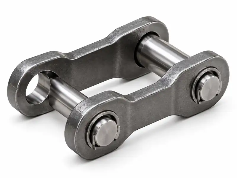
A link forms the repeated joint; a connecting element joins two structures; an attachment bracket supports something external; a plate may carry ground reaction or material. Determine the job before selecting a name.
Use An Orientation Sketch
Draw the machine direction, inner and outer chain faces and major bolt holes. This prevents a visually symmetric photograph from concealing a handed or offset component.
For this step, document the before-condition and the exact measurement or observation used to make the decision. If the part is already removed, show where it fitted by photographing adjacent components. Keep the photo identifier next to the measured value so it can be checked later.
Collect Key Dimensions
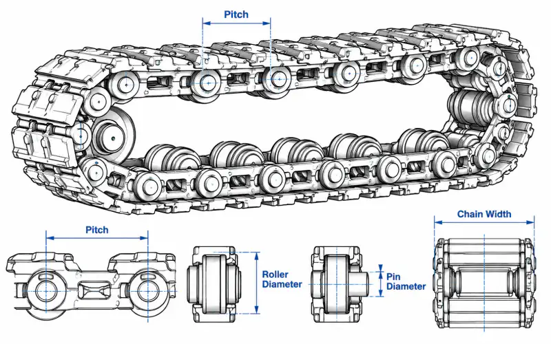
Mark pin centres, bore diameters, width between plates, component thickness, overall height and any special offsets. Include a scale and specify metric or imperial units.
A supplier reviewing collect key dimensions must know whether the figure is nominal drawing data, field measurement, or an estimate from a worn component. That distinction changes what can be quoted without a sample and what needs an additional dimensional inspection.
Check Adjacent Parts
Photograph the pieces that mate with the unknown component. A connection that looks standard may rely on a special spacer, end retainer or nonstandard boss.
For this step, document the before-condition and the exact measurement or observation used to make the decision. If the part is already removed, show where it fitted by photographing adjacent components. Keep the photo identifier next to the measured value so it can be checked later.
Prevent Misclassification
Do not copy a type name from a catalogue image when the installed part serves a different machine function. Treat uncertainty as a technical question to resolve before procurement.
Enquiry Data Checklist
| Thông tin đầu vào của người mua | Lý do để xác nhận |
|---|---|
| Machine context | Actual chain function, installation position, equipment model if known |
| Chain dimensions | Pitch across multiple joints, width and joint reference dimensions |
| Mounting interface | Attachment locations, hole pattern and sprocket relationship |
| Service context | Working medium, abrasion exposure and wear symptoms |
| Files | Measured sketch, installed photos, part reference, quantity |
Decisions That Require Verification
Manufacturing dimensions, material grade, heat treatment, permissible operating load and any substitute part reference have to be confirmed for the real ordered configuration. General chain geometry can support preliminary identification but cannot establish a guaranteed replacement by itself.
Even when a nominal chain pitch is known, examine the mating assembly. A repair that restores one joint but leaves severely worn sprocket teeth or distorted brackets unchanged may not address the underlying fault. Distinguish immediate maintenance work from a complete system replacement decision.
Technical Review Workflow
- Identify the machine function and which component is being discussed.
- Record the measured geometry with photographs and units.
- Check the mating chain, sprocket and attachment interface.
- Define the exact replacement scope and quantity.
- Submit the sketch and photos for configuration review.
Common Questions
What if the original part number is missing?
Use installed-machine views, a measured chain sample, photographs of the connecting components and a description of the duty.
Is a matching pitch enough to place an order?
No. Joint shape, width, roller geometry, mounting offset and sprocket engagement can differ at the same nominal pitch.
Can dimensions from a worn component be used?
Yes as a provisional starting point, but significant wear must be documented and compared with an unworn reference when possible.
How can a technical enquiry be reviewed efficiently?
Supply the actual application, photos with scale, readable sketch, link count, interface details and quantity.
Start With Mechanical Function
A chain component should be named according to the force or motion it handles, not only the way its silhouette looks. Determine whether it forms a repeating link, carries an attachment, joins two chain sections or interacts directly with a sprocket. Photographs may show substantial metal shapes but not the side that actually transmits force. A simple sketch with arrows for chain travel and load direction helps reveal the role. This is particularly important where catalogue pictures include both crawler and mining conveyor parts that share visually similar features.
Create An Orientation Record
Before removing the part, mark the outward face, machine side, direction of travel and connection to nearby plates. Photograph the fasteners and retainers before disassembly, keeping each image in a numbered sequence. With an unfamiliar assembly, pieces that appear mirror-symmetric may actually have offset bosses or hand-specific mounting faces. A labelled orientation record reduces the chance of ordering a part that physically matches one face but cannot be installed on the required side. Include a wide view of the mechanism to show what the detail belongs to.
Measure The Joint Profile
Record the distance between pin centers, inside and outside widths, plate thickness, pin-hole diameters and any shoulder lengths. On components with a mounted plate, add hole centers and vertical offsets from the chain joint axis. Avoid measuring only the longest visible dimension. A small change in an internal clearance can prevent articulation even where outside dimensions are similar. Keep worn values separate from drawing values and identify which surfaces show deformation. If the original nominal shape cannot be reconstructed safely, request an engineering review with the worn sample and related assembly drawings.
Inspect Connected Elements
No link works in isolation. A joint may include a pin, a bush, a roller, a spacer and retention hardware; a mounted attachment may also connect to a larger bar or plate. Assemble a simple parts map showing which items move together and which surfaces articulate. This helps distinguish a connecting link from a load-carrying bracket and reveals whether replacement parts should be ordered as a kit. When a chain guide or sprocket touches a particular surface, include that detail in the sketch because it can identify an otherwise ambiguous component.
Avoid False Interchange Claims
Matching an online photograph is a useful first step but is not a substitute for dimensions and mechanical compatibility. A replacement may share an outside profile yet differ at the pin axis, internal width or support contact point. Do not use brand names or nominal family labels to claim direct substitution without a checked drawing. In an enquiry, identify any missing values and the evidence available for verifying them. If one source image appears to represent a material conveyor part rather than a travelling track part, keep that uncertainty visible.
Organize The Final Package
Arrange the enquiry as machine overview, installed assembly, removed part views, dimensions, component count and required quantity. Use descriptive filenames and keep a concise list of open questions. If a workshop can supply a measured sketch, attach it alongside the unedited photographs. This provides enough context for a technical dialogue without implying that every part has already been identified. The resulting record can later become the basis for a model-specific product page once an approved configuration and real dimensions are confirmed.
Next Step
Use the measurement guides and product-family pages together. A clear enquiry record helps the technical team identify uncertainty before a replacement decision becomes expensive.