Description
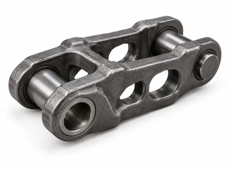
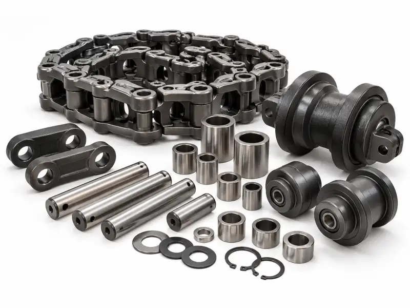
Individual chain joint hardware identification for worn, damaged or missing pins, rollers and bushings. Quotations require matched measurements.
Product Role
The crawler chain pins, rollers & bushings is evaluated by the real mechanical job it performs: supporting articulated chain joints and contact with running or guiding surfaces. The key specification work concerns joint diameter, clearance, roller outside diameter, working width and axial retention. Clear identification comes before any claim of machine interchangeability.
An engineering enquiry should distinguish the assembled part from the components around it. Differences in pin fits, spacing, attachment position and running clearance can be decisive even when two photographs show broadly similar metal profiles. Describe how the installed part moves and where it transfers force.
Construction And Interfaces
The neighbouring mechanical interfaces to review are link bores, bush seats, sprocket contact surfaces and neighbouring plate faces. These relationships should be documented by a drawing or an installed-machine photograph wherever possible. A free-standing image may omit the very faces that control assembly fit.
Record the orientation, working face, mounting fasteners, end retention and any direction-dependent geometry. Where the original assembly has been modified in the field, identify the modifications before asking for a nominal replacement. The current mechanical envelope, not only the original label, should guide the review.
Key Selection Variables
| Variable to identify | Verification requirement |
|---|---|
| Pin diameter and working length | Confirm using part drawing, measurement or the actual equipment installation |
| Roller outside diameter and face width | Confirm using part drawing, measurement or the actual equipment installation |
| Bushing inside/outside dimensions | Confirm using part drawing, measurement or the actual equipment installation |
| End retention and spacers | Confirm using part drawing, measurement or the actual equipment installation |
| Requested component quantities | Confirm using part drawing, measurement or the actual equipment installation |
Operating Conditions
Joint hardware is not interchangeable on appearance alone. Even a nominally similar roller can affect engagement, tracking and friction if its width or running profile differs.
Specify water, soil or debris exposure, operation cycle, lubrication access and the reason for replacement. Severe grit and difficult maintenance access often make joint protection and inspection planning particularly important, although the acceptable material and treatment must still be agreed for the ordered design.
Geometry Before Model Numbers
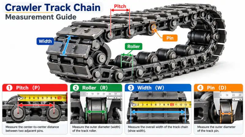
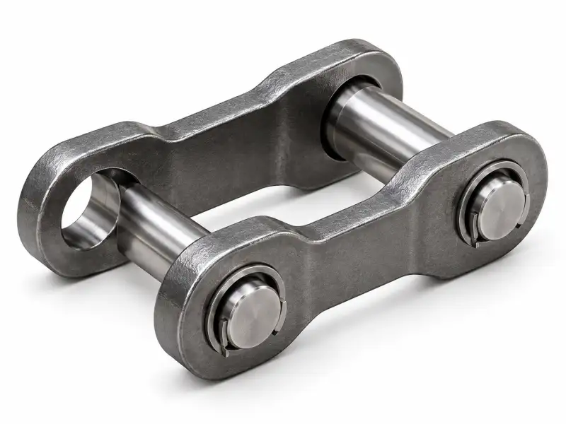
The useful first measurements are usually joint centre spacing, cross-sectional clearance and the contact surface that mates with the next component. If a worn part is the only reference, take measurements at several positions and disclose wear or deformation. A dimensional outline drawing is preferable to guessing a model number from a picture.
Measure the assembled installation wherever safe and practical. A separated link or attachment may lose its orientation once removed. Record adjacent components in the same photograph to establish the correct chain side and installation direction.
Integration And Installation
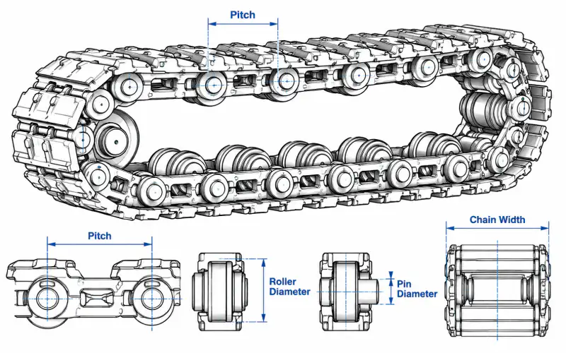
Confirm these parts before installation: link bores, bush seats, sprocket contact surfaces and neighbouring plate faces. Compare the overall running width, clearance to guards and frames, and the required joining or fastening procedure. A chain assembly that moves freely by hand may still contact a nearby part during a fully loaded travel cycle.
Installation instructions and tightening values must come from the approved machine and component drawings. Do not reuse a generic chain torque or fit specification unless the design and fastener class are confirmed. If the existing sprocket shows heavy hooking or wear, review it together with the new chain components.
Inspection And Wear
The main engineering risk is that installing replacement hardware without checking worn mating components can leave excess play or binding. Observe joint play, uneven wear, changes in surface contact and any deformation around mounting areas. Compare both sides or repeated links where feasible rather than relying on a single damaged component.
For a serviceable inspection record, show the position on the machine, measured condition and a photo with scale. Record which dimensions are affected by wear and which features remain good reference surfaces. A field photo does not establish material properties or load ratings.
Replacement Measurements
Suggested data collection: record clean diameters at multiple points and examine the wear pattern on both the pin and its surrounding bore. Add the total quantity, any urgent maintenance date and the country of destination. Mark if the request is for a complete chain strand, an individual link, a matched pair or repair hardware.
Drawing-Based Options
Possible engineering work can involve adapting geometry to a verified sample or creating a matched replacement set. Feasibility is reviewed against actual drawings, material requirements, measurement access and available inspection evidence. No unconfirmed alloy grade, maximum load or delivery promise is assigned to this generic product class.
If compatibility remains uncertain, request a small validation stage before a larger production order. That may include one physical sample, a full joint drawing or a controlled measurement review. The aim is to make fit assumptions visible before the parts are ordered.
Separate The Wear Components
Pins, bushes and rollers have different mechanical functions even when supplied together. A pin carries joint reaction through its engagement with adjacent links; a bush may provide an articulating or sacrificial surface; a roller can interact with guide or sprocket contact geometry. Confirm which pieces actually exist in the assembly before requesting a replacement kit. A photographed cylinder without surrounding parts cannot reveal which surface rotates relative to which other surface. A simple exploded sketch with arrows showing the joint order is a practical starting point for an engineering quotation.
Measuring Cylindrical Features
Use an undamaged sample to record outside diameter, inside diameter where present, overall length, working width, shoulders, grooves and end retention features. On a worn part, take readings at several angular positions to show possible ovality and distinguish nominal geometry from damage. Identify any lubrication hole or passage only if it is visible and part of the actual component. Do not assume a hardness specification from the appearance of a polished or dark surface. Exact material and treatment requirements should be established using original drawings or a documented engineering review.
Pairing The Joint Set
Replacing a single roller without considering its pin or bush may leave the assembled joint with unsuitable clearances. Compare mating parts together and identify which dimensions belong to the link, which belong to the rolling element and which belong to any spacer. Show how the joint is retained after assembly, especially if one side will be inaccessible in service. Inventory requests should specify whether the quantity means individual pins, complete joint sets or enough components for a specified number of chain links. That distinction prevents a technically correct item from arriving as an incomplete repair kit.
Technical Enquiry Checklist
- Pin diameter and working length
- Roller outside diameter and face width
- Bushing inside/outside dimensions
- End retention and spacers
- Requested component quantities
- Photos of installed mating parts
- Available drawing or sample reference
- Quantity, delivery destination and requested documentation
Frequently Asked Questions
What does roller diameter tell me about compatibility?
This depends on the actual mating parts, wear condition and operating role. A drawing or existing sample should be reviewed before deciding on repair or replacement.
When should a bushing be measured separately?
Record nominal drawing values separately from field dimensions and clearly indicate wear. Confirm pin or roller geometry, pitch and mounting layout wherever relevant.
Which wear patterns indicate an oversized joint clearance?
This depends on the actual mating parts, wear condition and operating role. A drawing or existing sample should be reviewed before deciding on repair or replacement.
Do parts need to be ordered as a matching set?
This depends on the actual mating parts, wear condition and operating role. A drawing or existing sample should be reviewed before deciding on repair or replacement.
Request A Configuration Review
Share photos, measured chain geometry and an equipment drawing to confirm whether this component class is appropriate. Provisional illustrations are not a substitute for a final itemized quotation.