Description
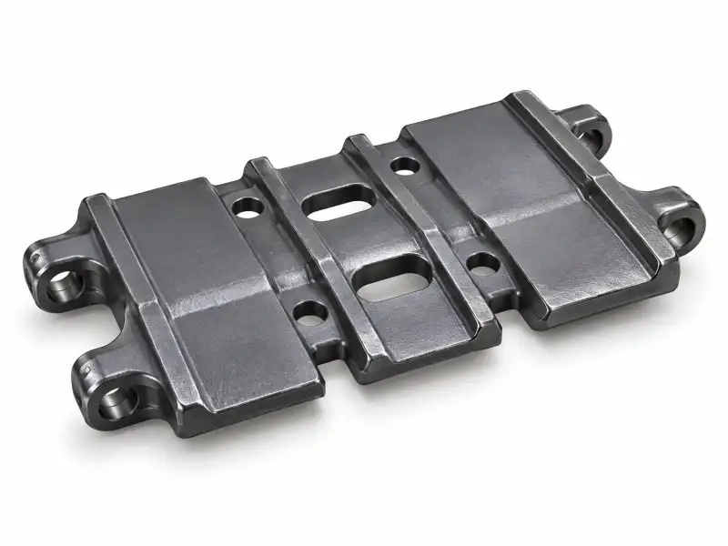
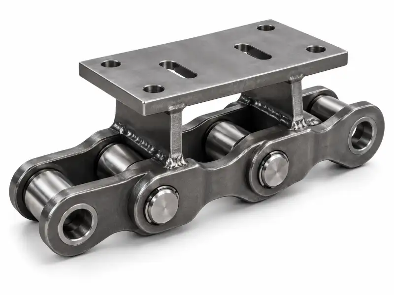
Plate-style chain component reference for identifying an existing mounting element. The actual role as track shoe, cover plate or conveying plate must be confirmed.
Product Role
The crawler track plate or mounting plate is evaluated by the real mechanical job it performs: creating a supported mounting or load-contact surface within a particular chain assembly. The key specification work concerns plate profile, mounting features and operational face orientation. Clear identification comes before any claim of machine interchangeability.
An engineering enquiry should distinguish the assembled part from the components around it. Differences in pin fits, spacing, attachment position and running clearance can be decisive even when two photographs show broadly similar metal profiles. Describe how the installed part moves and where it transfers force.
Construction And Interfaces
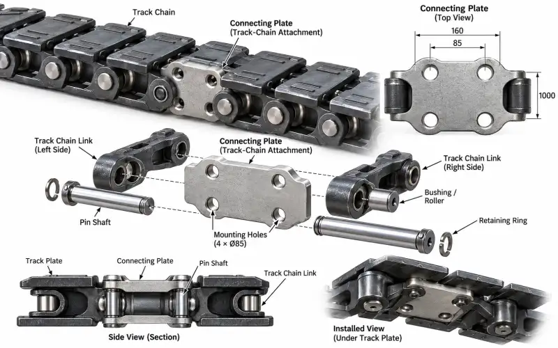
The neighbouring mechanical interfaces to review are chain attachment brackets, fasteners, adjoining plate edges and any contact surface. These relationships should be documented by a drawing or an installed-machine photograph wherever possible. A free-standing image may omit the very faces that control assembly fit.
Record the orientation, working face, mounting fasteners, end retention and any direction-dependent geometry. Where the original assembly has been modified in the field, identify the modifications before asking for a nominal replacement. The current mechanical envelope, not only the original label, should guide the review.
Key Selection Variables
| Variable to identify | Verification requirement |
|---|---|
| Plate size and flatness requirements | Confirm using part drawing, measurement or the actual equipment installation |
| Hole and slot locations | Confirm using part drawing, measurement or the actual equipment installation |
| Working-face shape and wear | Confirm using part drawing, measurement or the actual equipment installation |
| Attachment type and fastening | Confirm using part drawing, measurement or the actual equipment installation |
| Required quantity or assembly grouping | Confirm using part drawing, measurement or the actual equipment installation |
Operating Conditions
Plate components should be named from their actual installation, not from a background photo alone. This page supports identification and drawing-based enquiries rather than promising cross-equipment interchange.
Specify water, soil or debris exposure, operation cycle, lubrication access and the reason for replacement. Severe grit and difficult maintenance access often make joint protection and inspection planning particularly important, although the acceptable material and treatment must still be agreed for the ordered design.
Geometry Before Model Numbers
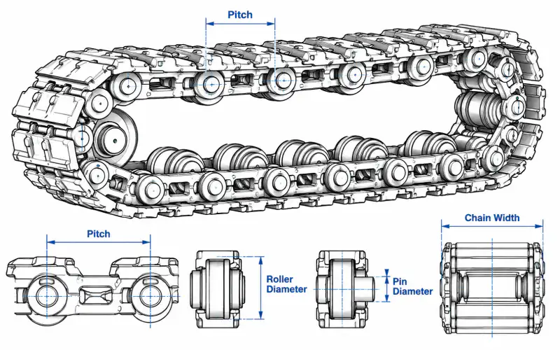
The useful first measurements are usually joint centre spacing, cross-sectional clearance and the contact surface that mates with the next component. If a worn part is the only reference, take measurements at several positions and disclose wear or deformation. A dimensional outline drawing is preferable to guessing a model number from a picture.
Measure the assembled installation wherever safe and practical. A separated link or attachment may lose its orientation once removed. Record adjacent components in the same photograph to establish the correct chain side and installation direction.
Integration And Installation
Confirm these parts before installation: chain attachment brackets, fasteners, adjoining plate edges and any contact surface. Compare the overall running width, clearance to guards and frames, and the required joining or fastening procedure. A chain assembly that moves freely by hand may still contact a nearby part during a fully loaded travel cycle.
Installation instructions and tightening values must come from the approved machine and component drawings. Do not reuse a generic chain torque or fit specification unless the design and fastener class are confirmed. If the existing sprocket shows heavy hooking or wear, review it together with the new chain components.
Inspection And Wear
The main engineering risk is that a plate from a conveyor mechanism may be visually similar to a track-related part while serving a different duty. Observe joint play, uneven wear, changes in surface contact and any deformation around mounting areas. Compare both sides or repeated links where feasible rather than relying on a single damaged component.
For a serviceable inspection record, show the position on the machine, measured condition and a photo with scale. Record which dimensions are affected by wear and which features remain good reference surfaces. A field photo does not establish material properties or load ratings.
Replacement Measurements
Suggested data collection: photograph the item in its installed position, then provide width, length, thickness, hole pattern and edge shape. Add the total quantity, any urgent maintenance date and the country of destination. Mark if the request is for a complete chain strand, an individual link, a matched pair or repair hardware.
Drawing-Based Options
Possible engineering work can involve adapting geometry to a verified sample or creating a matched replacement set. Feasibility is reviewed against actual drawings, material requirements, measurement access and available inspection evidence. No unconfirmed alloy grade, maximum load or delivery promise is assigned to this generic product class.
If compatibility remains uncertain, request a small validation stage before a larger production order. That may include one physical sample, a full joint drawing or a controlled measurement review. The aim is to make fit assumptions visible before the parts are ordered.
Contact-Surface Definition
A broad track plate can be a ground-contact shoe, a structural mounting plate or an element of a different moving machine. Its shape alone does not identify that purpose. First describe whether its underside engages soil, gravel, a support rail or a conveyor surface. Then record the location of the chain attachment relative to the working face. Wear on the bottom, leading edge and bolt holes provides clues about loading direction, but it does not establish an approved material grade. The quotation should refer to the actual installed system and should not combine plate dimensions from one machine with chain dimensions from another.
Plate Mounting Geometry
Make a flat drawing showing outside contour, plate width, mounting hole count, hole diameter, center-to-center spacing and any countersinks or slots. Add a side view for thickness, bends, ribs, raised bosses and welds. If the plate is curved or twisted from service, photograph an undamaged neighbor and the supporting frame to reconstruct orientation. On wide tracks, record the relationship between the plate and any paired chain strands. A close match in outline will not help if the holes sit a few millimeters away from the actual attachment centers; use verified drawing tolerances where provided.
Wear Pattern And Handling
The leading and trailing plate edges may wear differently depending on travel direction and turning duty. Compare plates from the center and edge of the track, and include one photo with the fasteners still installed. This identifies whether wear is primarily surface abrasion, loose mounting, impact or a tracking problem. Large metal plates can have hazardous pinch points, so provide handling and lifting requirements from the real part mass and approved procedure rather than assumptions. Confirm whether the order is for individual replacement plates, a complete track set or plates assembled to a new chain.
Technical Enquiry Checklist
- Plate size and flatness requirements
- Hole and slot locations
- Working-face shape and wear
- Attachment type and fastening
- Required quantity or assembly grouping
- Photos of installed mating parts
- Available drawing or sample reference
- Quantity, delivery destination and requested documentation
Frequently Asked Questions
How can I identify whether a plate is a track shoe?
This depends on the actual mating parts, wear condition and operating role. A drawing or existing sample should be reviewed before deciding on repair or replacement.
Which dimensions should appear on a sketch?
Record nominal drawing values separately from field dimensions and clearly indicate wear. Confirm pin or roller geometry, pitch and mounting layout wherever relevant.
Why is the surrounding assembly photo important?
Provide a front, side, end and installed view with a physical scale. Photos should show the relationship to the mating components rather than only a clean isolated part.
Can plates be quoted separately from chains?
This depends on the actual mating parts, wear condition and operating role. A drawing or existing sample should be reviewed before deciding on repair or replacement.
Request A Configuration Review
Share photos, measured chain geometry and an equipment drawing to confirm whether this component class is appropriate. Provisional illustrations are not a substitute for a final itemized quotation.